Selecting a quartz crystal often starts with frequency, package size, and a part number. But these specifications alone rarely tell the full story: reliable operation depends on how the crystal interacts with the oscillator circuit.
Figure 1. A crystal may look like a simple component, but its behavior is shaped by the oscillator circuit around it — from the target IC and load conditions to PCB parasitics, layout and operating environment.
(Source: WDI AG)
A crystal is not a standalone timing source. It is an electromechanical resonator that becomes part of an oscillator loop. Its behavior depends on the oscillator stage of the target IC, the load conditions, the PCB layout, the operating environment, and the way the circuit is validated. Two crystals with the same nominal frequency and package can therefore behave differently if their electrical parameters or circuit conditions do not match.
The right crystal is defined by the oscillator circuit in which it has to start reliably, operate over time, and remain within the application’s frequency limits.
Why Frequency and Package Alone Do Not Ensure Reliable Oscillator Operation
Frequency and package define the visible framework of the selection: clock frequency, footprint, and mechanical compatibility. But they do not indicate whether the oscillator will start reliably, whether the frequency will be where the application expects it, or whether the circuit will remain stable across temperature, aging, and manufacturing tolerances.
This becomes especially important when a design moves from prototype to series production, when an existing part is replaced, or when the same frequency is sourced from another manufacturer. A datasheet match on frequency and package may look convincing, but it does not prove that the oscillator will behave the same way on the final board.
Load Capacitance Is Specified for the Crystal, But Realized by the Circuit
The specified load capacitance is not simply the value of two external capacitors in the schematic. It is the effective load the crystal sees in the oscillator circuit. This load is influenced by external capacitors, oscillator input and output capacitances, PCB traces, parasitic capacitances, component placement, and grounding.
If the effective load differs from the value for which the crystal was specified, the oscillation frequency can shift. Whether that shift is relevant depends on the crystal and the application requirements.
The datasheet defines the intended load condition, but the PCB and oscillator circuit must create it in practice.
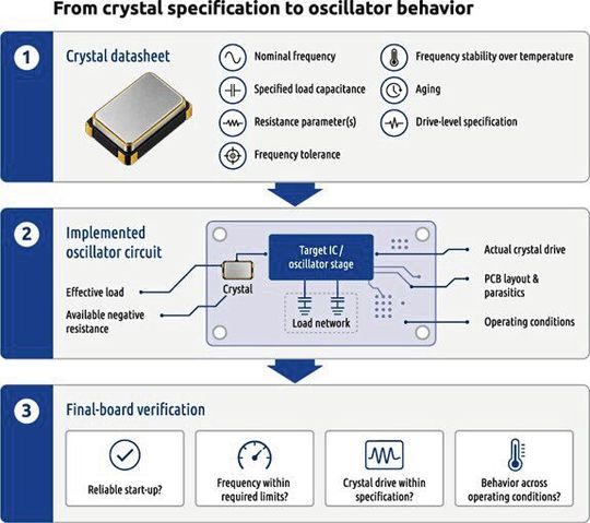
Figure 2. Crystal selection does not end with the datasheet. Specified parameters must be considered together with the target IC, load network, PCB parasitics and operating conditions, while the resulting oscillator behavior has to be verified on the final board.
(Source: WDI AG)
Crystal Resistance Parameters and Start-up Margin Belong Together
Another important point is the resistance value stated in the crystal datasheet. Depending on the manufacturer, product type, and measurement conditions, terms such as ESR, motional resistance, Rm, R1, or load-resonance resistance may be used differently. This is not a terminology exercise, but the distinction matters.
For oscillator start-up, the resistance parameter matters because it is part of the loss the oscillator circuit has to overcome. It is not the only factor, though. Reliable start-up also depends on available negative resistance, load conditions, supply conditions, temperature, layout, and production tolerances.
A lower resistance value is therefore not automatically the complete answer. The real question is whether the selected crystal and the oscillator stage have sufficient margin under final application conditions. The datasheet can support this decision, but it cannot replace verification in the actual circuit.
Drive Level: The Power the Crystal Really Sees
Drive level is often underestimated because it tends to be obscured by the oscillator circuit itself. It refers to the actual excitation or power experienced by the resonator during oscillator operation. It is not the supply voltage, not the logic level, and not simply the current consumption of the oscillator.
The oscillator circuit must drive the crystal sufficiently to initiate and sustain oscillation. If the oscillator drive or start-up margin is too low, reliable oscillation may be compromised. Excessive drive, on the other hand, can place unnecessary stress on the resonator and may affect long-term frequency stability.
Stand: 08.12.2025
Es ist für uns eine Selbstverständlichkeit, dass wir verantwortungsvoll mit Ihren personenbezogenen Daten umgehen. Sofern wir personenbezogene Daten von Ihnen erheben, verarbeiten wir diese unter Beachtung der geltenden Datenschutzvorschriften. Detaillierte Informationen finden Sie in unserer Datenschutzerklärung.
Einwilligung in die Verwendung von Daten zu Werbezwecken
Ich bin damit einverstanden, dass die Vogel Communications Group GmbH & Co. KG, Max-Planckstr. 7-9, 97082 Würzburg einschließlich aller mit ihr im Sinne der §§ 15 ff. AktG verbundenen Unternehmen (im weiteren: Vogel Communications Group) meine E-Mail-Adresse für die Zusendung von redaktionellen Newslettern nutzt. Auflistungen der jeweils zugehörigen Unternehmen können hier abgerufen werden.
Der Newsletterinhalt erstreckt sich dabei auf Produkte und Dienstleistungen aller zuvor genannten Unternehmen, darunter beispielsweise Fachzeitschriften und Fachbücher, Veranstaltungen und Messen sowie veranstaltungsbezogene Produkte und Dienstleistungen, Print- und Digital-Mediaangebote und Services wie weitere (redaktionelle) Newsletter, Gewinnspiele, Lead-Kampagnen, Marktforschung im Online- und Offline-Bereich, fachspezifische Webportale und E-Learning-Angebote. Wenn auch meine persönliche Telefonnummer erhoben wurde, darf diese für die Unterbreitung von Angeboten der vorgenannten Produkte und Dienstleistungen der vorgenannten Unternehmen und Marktforschung genutzt werden.
Meine Einwilligung umfasst zudem die Verarbeitung meiner E-Mail-Adresse und Telefonnummer für den Datenabgleich zu Marketingzwecken mit ausgewählten Werbepartnern wie z.B. LinkedIN, Google und Meta. Hierfür darf die Vogel Communications Group die genannten Daten gehasht an Werbepartner übermitteln, die diese Daten dann nutzen, um feststellen zu können, ob ich ebenfalls Mitglied auf den besagten Werbepartnerportalen bin. Die Vogel Communications Group nutzt diese Funktion zu Zwecken des Retargeting (Upselling, Crossselling und Kundenbindung), der Generierung von sog. Lookalike Audiences zur Neukundengewinnung und als Ausschlussgrundlage für laufende Werbekampagnen. Weitere Informationen kann ich dem Abschnitt „Datenabgleich zu Marketingzwecken“ in der Datenschutzerklärung entnehmen.
Falls ich im Internet auf Portalen der Vogel Communications Group einschließlich deren mit ihr im Sinne der §§ 15 ff. AktG verbundenen Unternehmen geschützte Inhalte abrufe, muss ich mich mit weiteren Daten für den Zugang zu diesen Inhalten registrieren. Im Gegenzug für diesen gebührenlosen Zugang zu redaktionellen Inhalten dürfen meine Daten im Sinne dieser Einwilligung für die hier genannten Zwecke verwendet werden. Dies gilt nicht für den Datenabgleich zu Marketingzwecken.
Recht auf Widerruf
Mir ist bewusst, dass ich diese Einwilligung jederzeit für die Zukunft widerrufen kann. Durch meinen Widerruf wird die Rechtmäßigkeit der aufgrund meiner Einwilligung bis zum Widerruf erfolgten Verarbeitung nicht berührt. Um meinen Widerruf zu erklären, kann ich als eine Möglichkeit das unter https://contact.vogel.de abrufbare Kontaktformular nutzen. Sofern ich einzelne von mir abonnierte Newsletter nicht mehr erhalten möchte, kann ich darüber hinaus auch den am Ende eines Newsletters eingebundenen Abmeldelink anklicken. Weitere Informationen zu meinem Widerrufsrecht und dessen Ausübung sowie zu den Folgen meines Widerrufs finde ich in der Datenschutzerklärung, Abschnitt Redaktionelle Newsletter.
The actual drive level is influenced by the oscillator circuit, the chosen crystal, the load conditions, and the PCB layout. It should therefore be considered together with the crystal specification and the oscillator guidelines of the target IC manufacturer.
Tolerance, Stability Over Temperature, and Aging Form One Frequency Budget
A crystal datasheet typically lists frequency-related parameters separately: initial tolerance, frequency stability over temperature, aging, and sometimes application-dependent effects. In the end application, these are not isolated table values. What matters is the combined clock behavior over time and across operating conditions. Initial tolerance, frequency stability, aging, and circuit-related frequency shifts must therefore be considered as one frequency budget.
That does not mean the values simply add together. Interpretation depends on the datasheet, measurement conditions, and application requirements. A crystal should not be selected because one parameter looks favorable while the overall budget remains unclear.
A tight initial tolerance may not be enough if the frequency stability over temperature does not fit the operating environment. A suitable temperature range may not be enough if the circuit load shifts the frequency outside the intended margin. The practical question is always the same: will the oscillator remain inside the frequency limits the application actually requires?
How PCB Layout and Circuit Validation Ensure Reliable Oscillator Operation
Even a carefully selected crystal can fall short if the PCB implementation is treated as an afterthought. The oscillator circuit is a sensitive analog function embedded within an otherwise digital system. Short trace lengths, controlled parasitics, proper component placement, solid grounding, and adequate distance from noisy signals can all influence oscillator performance.
The same physical effects that influence load capacitance can also affect start-up behavior and susceptibility to noise. Trace capacitance, coupling from fast digital signals, or insufficient grounding can shift the implemented circuit away from the conditions assumed during component selection.
The final proof is not the part number, but the behavior of the oscillator on the final board.
Validation means more than comparing datasheets. It means checking the oscillator in the target system, under realistic supply, temperature, layout, and start-up conditions. The required depth of validation depends on the application, but the principle is always the same: the oscillator must be verified where it will actually operate.
Specify the Full Application Requirements, Not Only the Crystal Parameters
The lesson for crystal selection is simple: do not start with the crystal alone. Start with the circuit it has to work in.
A useful crystal specification includes more than frequency, package, and tolerance. It should consider the target IC, intended load capacitance, relevant resistance parameter, operating temperature range, aging expectations, supply conditions, PCB environment, and validation requirements. Only then does the part number become the result of a design decision rather than a guess based on a few visible parameters.
This also matters later. If a design needs an alternative source, a smaller package, or a different tolerance, a complete specification makes the discussion more reliable. It shows which parameters are fixed, which are application-dependent, and which must be checked on the board. (mr)