Discrete DC/DC converters offer flexibility in cost, layout and thermal design. Realizing those benefits requires careful coordination of topology, magnetics and regulation—and a realistic assessment of development effort.
An isolated DC/DC converter is fundamentally based on two functionally critical components: a primary-side transformer driver or controller IC and a galvanically isolating high-frequency transformer.
(Source: RECOM)
A few watts of isolated auxiliary power may look straightforward on a block diagram. In practice, the supply must start reliably, handle changing loads and maintain the required isolation. When powering gate drivers in a fast-switching power stage, it must also tolerate rapid changes in potential across its isolation barrier. Its performance depends on the interaction of switches, transformer, rectification, filtering and PCB layout.
An integrated DC/DC module packages much of this engineering into a characterized component. A discrete implementation moves more responsibility to the system designer, while allowing voltages, component placement and heat dissipation to be tailored to the application. Lower component costs may offset the additional development effort at sufficient production volumes, but neither approach is inherently superior.
Coordinated portfolios of controller ICs, transformer drivers, rectifiers and magnetics offer an intermediate route between a finished module and a design developed entirely from scratch. Recom’s expansion from modules into discrete components illustrates this approach. Its initial focus on isolated auxiliary supplies is broadening toward additional topologies and power levels. The engineering question is how much such building blocks simplify development—and which decisions remain application-specific.
Define the Full Operating Envelope Before Selecting a Topology
Nominal input voltage and output power provide only a starting point. A useful specification also defines input tolerances and transients, minimum and maximum loads, allowable ripple, ambient temperature and cooling conditions. Isolation requirements and behavior during startup, shutdown and faults are equally important. A supply serving a nearly constant load faces different demands from one switching repeatedly between standby and full power.
For compact isolated converters, common options include push-pull, full-bridge and flyback architectures. Topology and regulation must be considered separately. A transformer driver may operate with a largely fixed duty cycle, leaving output voltage dependent on input voltage, turns ratio and load-dependent voltage drops. A full bridge does not provide closed-loop regulation simply because it uses four switches.
An unregulated supply can be appropriate when the input is stable and the load tolerates output variation. A wide input range or tight output tolerance generally requires feedback or another regulation stage. That stage adds losses, components and thermal constraints. The regulation concept therefore belongs in the initial architecture decision, rather than being added after the transformer and driver have been selected.
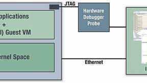
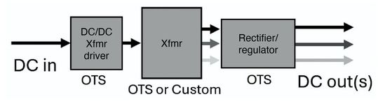
Figure 1. Block diagram of an isolated power supply using off-the-shelf (OTS) silicon, an OTS custom transformer, and one or more DC outputs. Recom flyback driver ICs provide feedback from either the primary or secondary side for internal voltage regulation.
(Source: RECOM)
Push-Pull and Full-Bridge Topologies: Understanding the Design Trade-Offs
A push-pull converter uses a center-tapped primary winding. Two switches alternately energize its two halves, driving the core in opposite magnetic directions. A full bridge uses four switches to reverse the voltage across a single primary winding, utilizing the entire primary during each active switching interval.
These arrangements differ in winding construction, conduction paths and voltage stress. A push-pull stage has one primary switch in the conducting path, whereas a full bridge has two. In a conventional push-pull circuit, however, the off-state switch ideally sees approximately twice the input voltage, before leakage-induced overshoot is included. Ideal switch blocking stress in a full bridge is approximately the input voltage. Both require suitable design margins.
Neither arrangement guarantees lower losses. The result depends on switch resistance, RMS current, winding resistance and switching behavior. Integration also matters. Recom’s RVP001 full-bridge driver combines P-channel and N-channel MOSFETs, while its RVP010 push-pull driver uses N-channel devices. Differences between those implementations cannot be attributed to topology alone.
Stand: 08.12.2025
Es ist für uns eine Selbstverständlichkeit, dass wir verantwortungsvoll mit Ihren personenbezogenen Daten umgehen. Sofern wir personenbezogene Daten von Ihnen erheben, verarbeiten wir diese unter Beachtung der geltenden Datenschutzvorschriften. Detaillierte Informationen finden Sie in unserer Datenschutzerklärung.
Einwilligung in die Verwendung von Daten zu Werbezwecken
Ich bin damit einverstanden, dass die Vogel Communications Group GmbH & Co. KG, Max-Planckstr. 7-9, 97082 Würzburg einschließlich aller mit ihr im Sinne der §§ 15 ff. AktG verbundenen Unternehmen (im weiteren: Vogel Communications Group) meine E-Mail-Adresse für die Zusendung von redaktionellen Newslettern nutzt. Auflistungen der jeweils zugehörigen Unternehmen können hier abgerufen werden.
Der Newsletterinhalt erstreckt sich dabei auf Produkte und Dienstleistungen aller zuvor genannten Unternehmen, darunter beispielsweise Fachzeitschriften und Fachbücher, Veranstaltungen und Messen sowie veranstaltungsbezogene Produkte und Dienstleistungen, Print- und Digital-Mediaangebote und Services wie weitere (redaktionelle) Newsletter, Gewinnspiele, Lead-Kampagnen, Marktforschung im Online- und Offline-Bereich, fachspezifische Webportale und E-Learning-Angebote. Wenn auch meine persönliche Telefonnummer erhoben wurde, darf diese für die Unterbreitung von Angeboten der vorgenannten Produkte und Dienstleistungen der vorgenannten Unternehmen und Marktforschung genutzt werden.
Meine Einwilligung umfasst zudem die Verarbeitung meiner E-Mail-Adresse und Telefonnummer für den Datenabgleich zu Marketingzwecken mit ausgewählten Werbepartnern wie z.B. LinkedIN, Google und Meta. Hierfür darf die Vogel Communications Group die genannten Daten gehasht an Werbepartner übermitteln, die diese Daten dann nutzen, um feststellen zu können, ob ich ebenfalls Mitglied auf den besagten Werbepartnerportalen bin. Die Vogel Communications Group nutzt diese Funktion zu Zwecken des Retargeting (Upselling, Crossselling und Kundenbindung), der Generierung von sog. Lookalike Audiences zur Neukundengewinnung und als Ausschlussgrundlage für laufende Werbekampagnen. Weitere Informationen kann ich dem Abschnitt „Datenabgleich zu Marketingzwecken“ in der Datenschutzerklärung entnehmen.
Falls ich im Internet auf Portalen der Vogel Communications Group einschließlich deren mit ihr im Sinne der §§ 15 ff. AktG verbundenen Unternehmen geschützte Inhalte abrufe, muss ich mich mit weiteren Daten für den Zugang zu diesen Inhalten registrieren. Im Gegenzug für diesen gebührenlosen Zugang zu redaktionellen Inhalten dürfen meine Daten im Sinne dieser Einwilligung für die hier genannten Zwecke verwendet werden. Dies gilt nicht für den Datenabgleich zu Marketingzwecken.
Recht auf Widerruf
Mir ist bewusst, dass ich diese Einwilligung jederzeit für die Zukunft widerrufen kann. Durch meinen Widerruf wird die Rechtmäßigkeit der aufgrund meiner Einwilligung bis zum Widerruf erfolgten Verarbeitung nicht berührt. Um meinen Widerruf zu erklären, kann ich als eine Möglichkeit das unter https://contact.vogel.de abrufbare Kontaktformular nutzen. Sofern ich einzelne von mir abonnierte Newsletter nicht mehr erhalten möchte, kann ich darüber hinaus auch den am Ende eines Newsletters eingebundenen Abmeldelink anklicken. Weitere Informationen zu meinem Widerrufsrecht und dessen Ausübung sowie zu den Folgen meines Widerrufs finde ich in der Datenschutzerklärung, Abschnitt Redaktionelle Newsletter.
Magnetic Balance Is Not the Same as Dead Time
Transformer operation depends on the voltage-time integral across the winding. For a given number of turns and core cross-section, this determines the change in magnetic flux density. In steady-state bipolar operation, positive and negative volt-second contributions must balance. An imbalance can shift the magnetic operating point toward saturation.
As the core approaches saturation, its effective magnetizing inductance falls and primary current rises sharply. Losses and switch stress increase. Symmetrical drive, suitable current limiting and adequate flux margin are therefore essential. Startup and fault recovery must also be assessed: acceptable steady-state waveforms do not establish safe behavior under every operating condition.
Dead time addresses a separate issue. It prevents unwanted overlap between conducting switches, particularly the upper and lower devices in a bridge leg, where simultaneous conduction creates a direct path across the supply. Short dead time increases the usable transfer interval, but must accommodate switching transitions and propagation delays. Defined dead time alone does not guarantee magnetic balance.
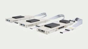
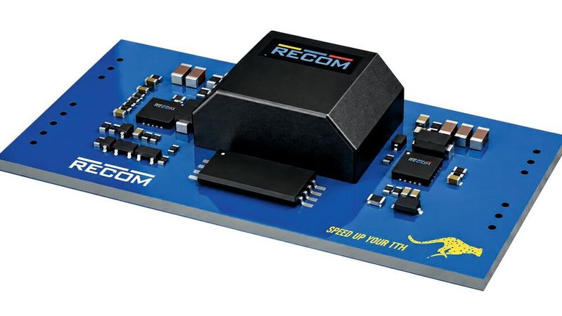
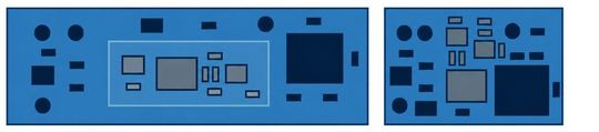
Figure 2. DC/DC modules (left) require fixed placement, whereas discrete solutions (right) are better suited for space-constrained PCB layouts.
(Source: RECOM)
Flyback Conversion Stores Energy Before Transferring It
A flyback converter operates differently. During the primary switch’s on-time, magnetizing current rises and energy is stored in the magnetic component. The secondary rectifier blocks during this interval. When the primary switch turns off, winding polarity reverses and energy is delivered to the secondary. Although commonly called a transformer, the magnetic component functions as coupled energy-storage inductors.
In discontinuous conduction mode, magnetizing current returns to zero before the next cycle. The energy stored per cycle can then be expressed ideally as E=½ · Lm · Ipk2. Transferable power consequently depends on magnetizing inductance, peak current, switching frequency and losses. In continuous conduction mode, stored energy remains at the start of the next cycle; current stresses and control behavior differ.
Flyback converters accommodate wide input ranges and multiple output windings. Multiple outputs, however, are not necessarily regulated equally well. If only one rail provides feedback, the others depend on winding coupling and their individual loads. Asymmetric loading can therefore require post-regulation or other measures to keep each rail within tolerance.
Leakage inductance adds another constraint. Its stored energy is not fully transferred to the secondary and can produce additional voltage stress when the primary switch turns off. Clamping and damping networks must control this behavior. Their losses, footprint and component stresses belong in the design budget; they are easily missed when comparing only controller ratings and nominal output power.
Where to Measure the Output Voltage: Primary- or Secondary-Side Regulation
Primary-side regulation, or PSR, estimates output voltage from a signal available on the primary side, for example an auxiliary winding voltage during secondary conduction. Sampling must take place at an appropriate point in the waveform. Switching-related ringing and load-dependent voltage drops can otherwise distort the estimate.
PSR avoids a separate feedback signal path across the isolation barrier. Its achievable accuracy nevertheless depends on the control method, winding coupling and treatment of voltage drops. Performance must be assessed across the specified input, load and temperature ranges. Eliminating an optocoupler describes a circuit implementation; it does not, by itself, establish regulation quality.
Secondary-side regulation senses the output directly and transfers control information across the isolation barrier. This can help meet tight voltage tolerances, but adds components and requires an appropriately designed feedback loop. Dynamic performance still depends on the complete converter. The output capacitor, power stage, feedback path and compensation jointly determine voltage deviation and recovery after a load step.
Magnetics Determine More Than the Turns Ratio
A transformer cannot be selected from turns ratio and nominal power alone. Relevant parameters include magnetizing and leakage inductance, current capability, winding resistance, isolation construction and the core’s suitability for the intended frequency and flux swing. Copper losses depend on RMS currents and winding resistance; at higher frequencies, skin and proximity effects alter current distribution. Core losses depend on material, frequency, flux excursion and temperature.
Parasitic capacitance between primary and secondary creates another coupling path. A changing potential across the isolation barrier drives displacement current, approximately according to i=C · dv/dt. This is particularly relevant for isolated gate-driver supplies in fast-switching SiC or GaN stages. Lower coupling capacitance can reduce these common-mode currents, but must be balanced against leakage inductance, winding resistance and insulation requirements.
An isolation test voltage also needs context. Short-duration dielectric testing, continuous working voltage and functional, basic or reinforced insulation describe different properties. Clearances, creepage distances, insulating materials and operating conditions must match the application. A transformer’s isolation rating does not automatically establish the compliance of the complete PCB assembly.
Beyond the transformer itself, secondary rectification and output filtering also shape converter performance, with rectification accounting for a substantial share of losses, especially at low output voltages. Diode conduction losses depend largely on forward voltage and current. Synchronous rectification replaces the diode conduction path with a controlled MOSFET and can reduce those losses. Its own operating consumption, gate-drive requirements and switching losses must still be considered across the actual load range.
The output capacitor supplies the load during intervals when the power stage does not deliver sufficient current. In a flyback converter, this includes the primary on-time. A first-order estimate of capacitive voltage change is ΔV≈I · Δt / C, with an additional contribution from equivalent series resistance. Selection must account for effective capacitance at operating bias, ripple-current capability and temperature. A short component list is not evidence that the filter is adequately dimensioned. Transformer, rectifier and output capacitor jointly determine losses, ripple and component stress.
Layout Freedom Comes With Electrical Constraints
Discrete construction allows heat sources to be distributed across a PCB and adapted to available cooling paths. This freedom has limits. Separating components too far can enlarge switching-current loops and increase parasitic inductance. Paths carrying rapidly changing currents should remain compact, while feedback and sensing connections need protection from switching interference.
Validation must extend beyond nominal input and load. Relevant conditions include low input voltage at high load, maximum input voltage, no load, load steps and restart after faults. At elevated ambient temperature, the transformer or rectifier may reach its limit before the controller. Integrated protection functions help manage specific faults but do not replace measurements of component stress and temperature distribution.
Compare Total Development and Production Costs
The bill of materials is only one part of the economic comparison. A discrete converter creates project-specific work in circuit design, PCB layout, prototypes, EMC optimization and qualification. A module transfers part of that effort to its manufacturer. It still requires validation in the end equipment, but can reduce the number of design iterations and the associated schedule risk.
Based on internal cost analyses, Recom cites approximately 50,000 units per year as a typical point at which discrete solutions may become attractive. This is a manufacturer-specific guideline, not a universal break-even threshold. The calculation depends on savings per unit, additional engineering expenditure, product lifetime and expected total production. Existing expertise and reusable designs can change the result significantly.
Matched IC-transformer combinations and reference designs can reduce the number of variables at the start of development. Their practical value depends on documentation of operating conditions, layout, thermal limits and test results. Reusing a circuit in a different system still requires checking its load behavior, isolation and EMC performance. Application support reduces uncertainty; it does not remove the need for system validation.
Outlook: From Auxiliary Converters to Power Architectures
Recom’s announced portfolio expansion illustrates the broader direction. Its initial emphasis on isolated solutions of roughly 1–30 W is intended to extend to 60 W, with additional controllers, buck regulators and LDOs. This would address non-isolated rails before or after the isolation stage as well as the isolated converter itself. The expansion includes roadmap items and should not be interpreted as a statement that every planned component is already available.
Combining these functions creates additional architecture options. A buck converter can reduce an intermediate voltage, an isolated stage can provide potential separation, and an LDO can post-regulate a sensitive rail. Each added stage also affects total efficiency, heat generation and startup sequencing. In particular, LDO dissipation increases with input-to-output voltage difference and load current.
The manufacturer is also investigating discrete AC/DC solutions. These introduce further mains-side protection, insulation and EMC requirements, limiting how directly low-voltage DC/DC experience can be transferred. The value of a broader component portfolio will ultimately depend on well-characterized combinations and useful application guidance. A building-block approach can simplify selection and development, but dependable operation remains a property of the complete power supply. (mr)